Prototyping for Design and Evaluation
Contents
What is Prototyping?
Prototypes are experimental and incomplete designs which are
cheaply and fast developed. Prototyping, which is the process of
developing prototypes, is an integral part of iterative user-centered design
because it enables designers to try out their ideas with users and to gather
feedback [1].
The main purpose of prototyping is to involve the users in testing design
ideas and get their feedback in the early stage of development, thus to
reduce the time and cost. It provides an efficient and effective way to
refine and optimize interfaces through discussion, exploration, testing
and iterative revision [2]. Early evaluation can be
based on faster and cheaper prototypes before the start of a full-scale
implementation. The prototypes can be changed many times until a better
understanding of the user interface design has been achieved with the joint
efforts of both the designers and the users.
Prototyping can be divided into low-fidelity prototyping, medium-fidelity
prototyping and high-fidelity prototyping. In some literature, it
is only simply classified as low-fidelity prototyping (also called Lo-Fi)
and high-fidelity prototyping (also called Hi-Fi), where low-fidelity prototyping
is mainly about paper-based mock-up, and high-fidelity is mainly about
computer-based simulation. The determining factor in prototype fidelity
is the degree to which the prototype accurately represents the appearance
and interaction of the product, not the degree to which the code and other
attributes invisible to the user are accurate. On this web page, we will
consider a fully-functioned prototype as a high-fidelity prototype. Other
prototypes will be divided into low-fidelity and medium-fidelity prototypes.
We will focus on the low-fidelity and medium-fidelity prototyping techniques.
Medium-fidelity and high-fidelity prototypings are discussed together on
some attributes indicated as medium(high)-fidelity prototyping.
Low-fidelity prototypes are quickly constructed to depict concepts,
design alternatives, and screen layouts, rather than to model the user
interaction with a system. Low-fidelity prototypes provide limited
or no functionality. They are intended to demonstrate the general look
and the feel of the interface, but not the detail how the application operates.
They are created to communicate and exchange ideas with the users, but
not to serve as a basis for coding and testing. A facilitator who knows
the application thoroughly is generally needed to demonstrate the prototype
to the users [2].
In contrast, high-fidelity prototypes are fully interactive, simulating
much of the functionality in the final product. Users can operate
on the prototype, or even perform some real tasks with it. High-fidelity
prototypes are not as quick and easy to create as low-fidelity prototypes,
but they faithfully represent the interface to be implemented in the product.
Medium-fidelity prototypes partially simulate the system interaction and
functionality.
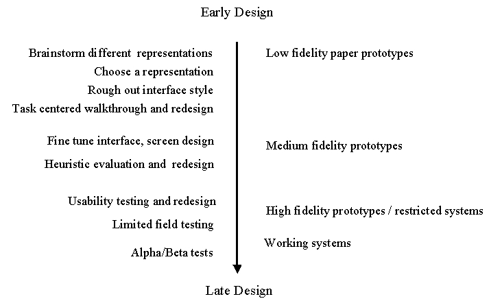
Figure 1 shows the transition of techniques from low-fidelity prototyping
to high-fidelity prototyping. However, the fidelity degree of each technique
may vary in diffirent practice. All of the techniques except the
fully-functioned high-fidelity prototyping will be discussed on this web
page.
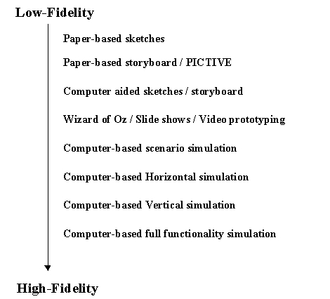
Figure 1. Transition of Prototyping Techniques
Introduction to Prototyping
Techniques
 Low-fidelity prototyping
 Sketches
Sketching techniques, a kind of visual brainstorming, can be
useful for exploring all kinds of design ideas. After producing initial
sketches the best ideas can be further developed by constructing cardboard
representations of the design, which can be evaluated with users. This
can then be followed by developing scenarios, software or video prototypes.
Freehand sketches are essential for crystallizing ideas in the early
stages of design. Through the act of putting ideas down on paper and inspecting
them, designers see new relations and features that suggest ways to refine
and revise their ideas. Sketches make apparent to designers not only perceptual
features but also inherently non-visual functional relations, allowing
them to extract functions from perception in sketches.
The type of mock-up depends on how advanced the idea is. It may be quicker
and cheaper to use paper-and-pencil forms at early stages, whereas computer-based
prototypes may be important in later stages for exploring and demonstrating
interaction and design consistency.
As one can imagine, the sketch technique is as simple as drawing the
outward appearance of intended system on paper. However, creativeness is
needed. There are some useful training exercises in [1]
to help designers get used to visual thinking. Figure 2 is a sketch
of a screen design.
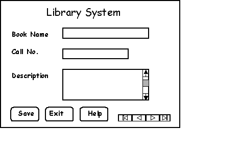
Figure 2. A Sketched Screen Design
Besides paper-and-pencil work, sketches can also be made with the aid
of computer software, such as the Paint package in Windows(R)
and SILK [11]. SILK allows designers to quickly sketch
an interface electronically and interactively. Figure 3 is a sketch created
by SILK.
Figure 3. Sketched Application Interface Created with SILK
Storyboard
Storyboard origins from the film industry, where a series of
panels roughly depicts snapshots from an intended film sequence in order
to get the idea about the eventual scene.
Storyboard is a graphical depiction of the outward appearance of the
intended system without accompanying system functionality. Storyboard provides
snapshots of the interface at particular points in the interaction so that
the users can determine quickly if the design is heading in the right direction.
Storyboards do not require much in terms of computing power to construct,
in fact, they can be mocked up without the aid of computers. The materials
needed are office stationery, such as pens or pencils of different colors,
Post-ItTM, stickers, and so on. However, modern graphical drawing
packages make it possible to create storyboards with the aid of a computer
instead of by hand. It is also possible to provide crude but effective
animation by automated sequencing through a series of snapshots [3].
For example, SILK [11], as we mentioned above, provides
electronical storyboarding function.
Figure 4 illustrates how storyboard is used to represent the system
function and sequence .
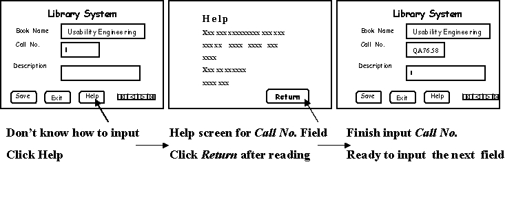
Figure 4. An Example of Storyboard
PICTIVE
PICTIVE stands for Plastic Interface for Collaborative Technology
Initiatives through Video Exploration. It was developed at Bell Communications
Research (Bellcore) in 1990 within the context of participatory design.
The initial experiments of PICTIVE were conducted by Muller and his group
in their projects [4]. It is an experimental participatory
design technique that is intended to enhance user participation in the
design process.
The rationale behind PICTIVE is the methodology of participatory design.
PICTIVE insures that users have early exposure to the target implementation
technology. The PICTIVE technique provides a fine-grained, dynamic paper
and pencil concretization mock-up of what the system will eventually look
like and how it will behave. The components are literally made of colored
plastic. Their relative durability and inexpensiveness encourage an atmosphere
of exploration and invention. The PICTIVE mock-up is intended to be extensively
modified in real-time by the users. PICTIVE is less as a means for the
evaluation of an already-designed interface, but rather for the creation
of the design of an interface.
PICTIVE was begun in reaction to software rapid prototyping environments,
in which developers have a disproportionate design impact, but non-computer
users are relatively disempowered by the complexity of current software
prototyping environments. The PICTIVE techniques were designed to be used
by people who were not necessarily programming professionals, so all participants
have equal opportunity to contribute their ideas.
The apparatus for PICTIVE includes video camera and a collection of
design objects. The design objects fall into two categories. The first
category is simple office materials, including pens, high-lighters, papers,
Post-ItTM, stickers. labels and paper clips -- all in a range
of bright colors. The second category is materials prepared by the developer,
such as menu bars, dialogue boxes, special icons for the project and so
on.
The procedures of PICTIVE are as follows.
First, both the users and the developers are asked to prepare a "homework".
Typically, the users are asked to think about task scenarios, for instance,
"what you would like the system to do for you and what steps are required
to finish the job". The developers need to construct a preliminary set
of system components for the users to manipulate based on prior discussions
with the users. Figure 5 shows some of such components made of plastic
[4].
Second, during the PICTIVE session, both the users and developers manipulate
the design objects on a design surface, where the designs are put together
as multiple layers of sticky notes and overlays that can be changed by
simple colored pens. Each participant brings her or his expertise. The
resulting design is not driven by any single participant, but represents
a synthesis of the different participants' different views. The users'
work scenarios are explored in detail, leading to a discussion of how the
developers' technology can be applied to meet the users' human needs. A
coordinator may be needed to keep the group on track.
A video camera is focused on the design objects and to record the voices
of the design team as they manipulate those objects. The video record of
the design session will serve as a dynamic presentation of the design.
Figure 6 illustrates a scene in the PICTIVE session [4].
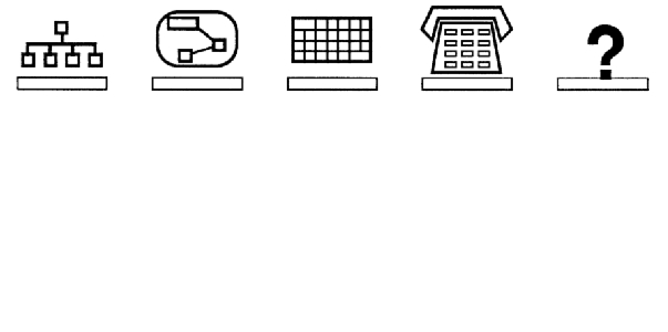
Figure 5. PICTIVE Plastic "Icons"
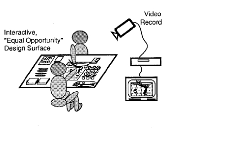
Figure 6. PICTIVE Setting
PICTIVE is especially suited for prototyping activities carried out
as part of a participatory design process since the low-tech nature of
the materials make them equally accessible to both the users and the developers.
In general, PICTIVE appears to be appropriate in circumstances similar
to those of knowledge-based system development, i.e., when there are users
available who understand what they need from the product or the project
.
More studies on PICTIVE had been conducted and described in [13]
. In [14], an experimental object-oriented software
prototype named TelePICTIVE was introduced. TelePICTIVE was designed to
allow naive as well as expert users to work together in designing GUIs
based on the PICTIVE paper participatory design methodology. [15]
introduced how to practice design exercises derived from the PICTIVE method.
Sample
steps of building a low-fidelity prototyping [9]
 Assemble a kit
- white, unlined, heavy paper, size 11 by 17 inches is nice
- hundreds of 5-by-8-inch cards as construction material or notes cards
- various of adhesives: tape, glue sticks, Post-ItTM, white
correction tape
- various of markers: colored pens and pencils, highlighters
- lots of sticky note pads of various sizes and colors
- acetate sheets to make overhead presentations
- scissors, knives, straightedges, Band-AidsTM
Set a deadline
No matter how hard you think about it, you are not going to
start getting it right until you put something in front of actual users
and start refining your idea by their experience with your design.
Construct models, not illustrations
Make a working model, for example, make the menus dropping
down, dialogs popping up, selection highlights and so forth. Photocopier
can be useful.
Preparing for a test
Select people who are the users or similar to the users to
test your prototype.
Write a set of scenarios, describing the product during use in a typical
work situation.
Conduct several dry runs before tests with people outside. Check if
there are missing components, confusing representation, etc. Make people
in the team familiar with the prototype.
Conducting a test
Team members are assigned different tasks. The greeter welcomes
and tries to put users at ease. Facilitator takes the lead, giving user
instructions, encouraging them to express their thoughts, making sure everything
gets done on time. One team member acts as the "computer". He or she knows
the application logic thoroughly, and sustains the illusion that paper
prototype behaves similar to a real computer. The rest of the team are
observers who take notes.
It is recommended to use a video camera during the test.
Evaluating results
Sort and prioritize the note cards. The team works through
the piles of cards and agrees on suggested changes.
Table
1 gives a brief comparison of the three low-fidelity prototyping techniques.
|
Techniques
|
Advantages
|
Disadvantages
|
|
Sketches
|
*very simple & cheap |
*must concentrate on high
level concepts
*hard to envision the
progression |
|
Storyboard
|
*simple & cheap
*users can evaluate the
direction of the interface is
heading |
*can only roughly display the
system interaction
*HCI expertise needed
|
|
PICTIVE
|
*simple & cheap
*fine-grained, dynamic
paper represents the system
interaction
*encourage users' modification |
*video needed
*HCI expertise needed
|
Table 1: Comparison of Low-fidelity Prototyping Techniques
Medium-fidelity
prototyping
Computer-based simulation
Medium-fidelity prototypes simulate or animate some but not
all features of the intended system. There are three approaches to limit
prototype functionality [6].
Vertical prototyping
Vertical prototyping cuts down on the number of features, so
that the result is a narrow system that includes in-depth functionality,
buy only for a few selected features.
Vertical prototypes allow users to perform and test some real tasks.
Horizontal prototyping
Horizontal prototyping reduces the level of functionality so
that the result is a surface layer that includes the entire user interface
to a full-featured system without underlying functionality.
Horizontal prototypes allow users to feel the entire interface, even
though they can not perform any real tasks.
The main advantages of horizontal prototypes are that they can be implemented
fast with the use of prototyping and screen design tools, and they can
be used to assess the interface as a whole.
Scenario
Scenario reduces both the number of features and the level
of functionality. It can simulate the user interface as long as the user
follows a previously planned path, i.e., a user can use a specific set
of computer facilities to achieve a specific outcome under specified circumstances.
Scenarios can be easy and cheap to build, and to be used during early
evaluation of a user interface design to get user feedback without the
expense of constructing a running prototype. It can also be used for user
testing if they are developed with slightly more detail than a pure narrative.
The concepts of vertical, horizontal and scenario prototyping are illustrated
in Figure 7 [6].
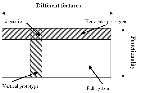
Figure 7: Two Dimensions of Prototyping
Computer-based prototypes become easier to implement than before because
there are more and more software prototyping tools, such as RAPID
[1], HyperCard [1], CHIRP [12].
Besides, there are many easy-to-learn and easy-to-use 4th generation languages,
such as Smalltalk and Microsoft Visual Basic(R).
Wizard of Oz
This is a method of testing a system that does not exist. It
allows designers to test ideas without implementation a system.
The Wizard of Oz technique works as follows: the user interacts with
a screen, but instead of a piece of software responding to the user's requests,
a developer (the wizard) is sitting at another screen (generally in another
room) simulating the system's intelligence and interacting with the user
[1]. The wizard may simulate all or part of the system
function. When setting up a Wizard of Oz simulation, experience with previously
implemented systems is helpful in order to place realistic bounds on the
wizard's "abilities" [10].
Early study of Wizard of Oz was the "listening typewriter" [5]
simulation of a speech recognition interface where the user's spoken input
was typed into a word processor by a human typist located in another room
[6]. Wizard of Oz is usually used for the design of
intelligent system [10], the experiment and development
of natural-language recognition system [16], and the
simulation of the system function which is difficult to implement in a
prototype.
Wizard of Oz is ideal for the testing of preliminary prototypes and
to gather users' expectations on the system. With this technique, the developers
can develop a limited functionality prototype and enhance its functionality
in evaluation by providing the missing functionality through human intervention
without cost on programming. Extra understanding of the users can also
be achieved through being involved so closely with the users.
Slide
shows and video prototyping
These techniques use the communication media to facilitate
prototyping.
In slide shows, the storyboard prototype is encoded on a computer with
software tools. The scene transition is activated by simple user input.
The slides form a simple horizontal or vertical prototype.
Video prototyping eliminates software limitations. It requires no post-production
editing or any special expertise in video production. The studies and experiments
with video prototyping can be found in [17] and [18].
It is more like Muller's PICTIVE work [4], where multi-disciplinary
design teams use it in informal brainstorming sessions. Unlike PICTIVE,
video prototyping does not simply record design ideas, but create an evocative
simulation of the proposed interface.
Here is an example of how to make video prototype for a pull down menu
[17]. First, we draw a menu bar on paper and
a mouse arrow on clear acetate. Second, turn on the camera and move the
acetate so that it looks as if the mouse is moving over the menu bar. When
the mouse is over the menu title, we make a clicking sound and pause the
camera. In the third step, we draw the menu on a small piece of paper,
put it under the menu title, and restart the camcorder. When viewing the
tape, the menu appears to have been pulled down from the menu bar.
Both slide shows and video prototyping provide kind of simulation of
the system. They appear to behave as a real system although they only show
some scenes. The simulation is restricted by some tightly predefined tasks,
and the user is hardly to interact with the system.
Table
2 gives a brief comparison of the medium-fidelity prototypings.
|
Techniques
|
Advantages
|
Disadvantages
|
|
Vertical
|
*test in depth under
realistic circumstances
*test with real user tasks |
*only test a limited part
of the system |
|
Horizontal
|
*test the entire interface
*can be implemented
fast |
*can not perform real
tasks |
|
Scenario
|
*easy and cheap to build |
*only test a limited part
of the system
*can not perform real
tasks |
|
Wizard of Oz
|
*save time on programming
*extra understanding of users can
be achieved by closely involved
with them |
*people need to be
trained to act as
computers
*less realistic |
|
Slide and video Simulation
|
*simple
*system simulation |
*lack of flexibility
*users can not interact
with the system |
Table 2: Comparison of Medium-fidelity Prototyping Techniques
When, Where and How to Use the
Prototyping Method
Comparison of low-fidelity and medium(high)-fidelity prototyping
[2]
|
Type
|
Advantages
|
Disadvantages
|
|
Low-Fidelity
|
*less time & lower cost
*evaluate multiple
design concepts
*useful communication
device
*address screen layout
issues
|
*limited usefulness for
usability tests
*navigational and flow
limitations
*facilitator-driven
*poor detailed
specification
|
|
Medium(high)-Fidelity
|
*partial/complete
functionality
*interactive
*user-driven
*clearly defines
navigational scheme
*use for exploration and
test
*marketing and sales tool |
*time-consuming to
create
*inefficient for
proof-of-concept designs
*blind users to major
representaional flaws
*managements may think
it is real |
Table 3: Comparison of Low-fidelity and Medium-fidelity Prototyping
Considerations when choosing prototyping techniques [2]
Although prototyping is recognized as an efficient way in interface
design, the optimum methods of prototyping have not yet been agreed upon.
There is a long time debate about which prototyping approach is better,
low-fidelity or high-fidelity. The list below summarizes some of the key
points to consider when deciding whether a low or medium(high)-fidelity
prototyping approach would be most appropriate for your design and development
needs.
Cost and schedule
constraints
If your budget and schedule are limited, you should first consider
low-fidelity prototyping, especially paper mock-up, because they are very
cheap and fast to develop. If there are experienced programmers and you
have fast tools to build a computer-based prototype, medium-fidelity prototyping
is also a consideration. High-fidelity prototyping is not recommended because
it is expensive to build.
Proof-of-concept
Low-fidelity prototyping is the most efficient way to test design ideas
because it is concentrated on the concept evaluation of a design. Medium(high)
prototyping will not help more, however, you spend more time and
money on a Medium(high)-fidelity prototype than on a low-fidelity one.
Navigation and flow
Medium-fidelity prototyping is good to simulate the system's interaction.
In low-fidelity prototyping, storyboard can show the system's direction.
User driven or facilitator-driven
If you need a user-driven prototype, medium(high)-fidelity prototyping
is recommended because users can directly interact with the prototype.
Otherwise, if you need a facilitator-driven prototype, low-fidelity prototyping
is the choice.
Look-and-feel the product
Medium(high)-fidelity prototyping can help users gain the feeling of
how the product works. If using a low-fidelity prototype, you must be good
at facilitating the prototyping process. You need to know clearly what
the real system will work, and you need to show and explain to cycle to
the users.
Usability test
Medium(high)-fidelity prototyping are good for usability tests because
they provide a relatively realistic appearance and functionality which
is close to the final product. The usefulness that low-fidelity prototyping
provides is too limited to conduct an usability test.
What is your facilitation skill/programming
skill
If there are people who have the expertise in human-computer interaction
and facilitation, low-fidelity could be the choice because running a low-fidelity
prototyping needs such experience. However, if there are people who are
experienced programmers, and you also have fast tools for interface generation,
medium(high)-fidelity prototyping could be considered. Even though generally
medium(high)-fidelity prototyping needs more time than low-fidelity prototyping,
the expertise in programming and efficient tools could reduce the time
and energy.
What development stage
you are
Figure 8 on this web page shows the relationship of prototyping and
product development.
If you are in the very early stage of the design, low-fidelity prototyping
will be efficient to help you work out the design concepts with the users.
If you are in the medium stage, such as screen design and usability
testing, medium-fidelity prototyping will be more useful.
Integrate
prototypes and products
The relationship of prototypes and final products is as follows:
Throw-away
Prototypes only serve to elicit users' reaction and to evaluate design
ideas. Prototypes will be thrown away in the later development phases.
Such prototypes must be created rapidly and cheaply. Otherwise it will
be too expensive to do prototyping.
Incremental
Product is built as separate modules. Each module is prototyped and
tested, then added to the final system.
Evolutionary
A prototype is built from low-fidelity to high-fidelity, incorporating
design changes, Eventually the prototype becomes the final product.
The Performance of Prototyping
on Some Attributes
Is it quick and cheap to
do?
Low-fidelity prototyping is fast and cheap to do because it is paper-based
and provides limited or no functionality. Medium(high)-fidelity prototyping
is more expensive than low-fidelity because it is interactive and provides
partial or full functionality. Coding and debugging is needed in a computer-based
prototyping.
Does it provide for controlled
study?
Low-fidelity prototyping is good for participatory design, but not
for controlled study because of their inherent restrictions, i.e., they
can not simulate the system interaction so that the users can not perform
tasks without facilitator's instructions. Medium(high)-fidelity prototyping
can simulate system interaction. However, the simulation is not very realistic,
so that the controlled study based on prototypes will be less reliable.
Is it suitable for qualitative
analysis?
Prototyping is suitable for qualitative analysis. Prototypes provide
a way for users to react to the conceptual design of a system, or to interact
with a simulation of a system. Qualitative methods such as introspection,
direct observation, heuristic evaluation are commonly used in evaluation
of the design. Comparing to the evaluation of a final product, qualitative
results, such as users' feedback and discussion are important in evaluation
of a prototype.
Is it suitable for quantitative
analysis?
Low-fidelity prototyping is not suitable for quantitative analysis.
Low-fidelity prototypes are too conceptual for a quantitative study.
Medium(high)-fidelity prototypes, especially computer-based ones,
can be used to get quantitative results, such as the users speed of performing
a task and the errors they made. But the results will not be very realistic
based on prototypes.
Does it require special equipment?
Low-fidelity prototyping does not require special equipment. Video
camera may be needed, for example, in the video prototyping and PICTIVE
prototyping.
Prototyping software is needed for computer-based prototypes.
Does it require special personnel?
Paper prototyping generally requires a facilitator, who knows the application
thoroughly, to demonstrate or to test the application. The user is dependent
on the facilitator to respond to the user's commands to turn cards or advance
screen to simulate the flow of the application. The expertise in application
and human-computer interaction is required.
Computer-based prototyping requires people with expertise in programming.
Working Examples
Windows(R) 95 user interface prototyping and usability testing
[7]
The design process of Windows 95 is used here
as an example because:
(1) it shows how to design and develop the user interface
for a large commercial software
(2) we can see how prototyping helps the designers and developers in
the both the design and evaluation process
(2) people are familiar with the interface of Windows
95, so that no domain knowledge of the product is needed
In the project, an iterative design was selected other
than a traditional "waterfall" design. In a "waterfall" design, the design
of the system is usually limited to a specification writing phase, and
the usability testing typically occurs near the end of the process. In
this project, people needed much more opportunity to create a design, try
it out with users, make changes, and gather more user feedback.
The iterative design was divided into three major phases:
exploration, rapid prototyping, and fine tuning. Paper or computer-based
prototypes were used to try out design ideas and to gather usability data
in the lab.
Figure 9 outlines the process.
Figure 9: Windows 95 Iterative Design Process
Exploration phase
In this phase, the purpose is to set design directions and
to gather initial user data.
An early prototype of the desktop was developed, with which the users
can interact with some functions the group concern about. The usability
studies of the prototype desktop were conducted in the Microsoft usability
lab. Questions addressed were sometimes very broad ("Do users like it"),
sometimes very specific ("After ten minutes of use, do users discover drag
and drop to copy a file?"). Data collected included: verbal protocol, time
per task, number of errors, types of errors, and rating information.
Test results showed that the design ideas about consistency with Window
3.1 were wrong. New design direction must be set up.
Rapid iteration phase
To save time, the team decided not to change the paper specification.
Instead, they let the prototypes and code serve as a "living" specification.
It allowed them to iterate at top speed.
They chose the major areas of the product function for iterative design
and testing. They mocked up a number if representations in Visual Basic
and tested them with users of all experience levels. In some tests comprehensive
Visual Basic prototype is used. Figure 10 and 11 are examples for part
of their prototypes. Some function and outlook of the prototypes, such
as the design of Task Bar, is developed in the final product in the process
of iterative design and evaluation.
Figure 10: "Plate" Visualization for Minimized Windows

Figure 11: Task bar
Fine tuning phase
Once they had designed and tested all of the major areas of
the product, they realized that they had to see how all of the pieces fit
together. Summative lab testing and longitudinal field study based on beta
version of Windows 95 were conducted.
Conclusion
Iterative design, using prototypes and the product as the specification,
and the constant testing with users allowed them to explore many different
solutions to problems quickly. They had essentially found that the prototype
was a richer type of specification. A prototype invites richer feedback,
because the reviewer has to imagine less about how the system would work.
In this example it is seen that computer-based medium(high) prototypes
played an important role in the iterative design, both in the specification
phase or in the design phase. Computer-based prototypes enabled the team
to conduct usability testing. The final product evolved from the process
of prototyping and testing.
Design
of network scenario generation tool
The network scenario generation tool was a course project I
did last year. Different from the example above, it was a small, non-commercial
software. It is an user interface for ATM-TN, an ATM network traffic simulation
program [8].
Low-fidelity paper prototyping was used since there were no time and
necessity to develop a computer-based prototype for such a small tool.
In the meetings with the users, I sketched the interface on paper and
described the flow of the operation. Since the users are computer experts,
they had no difficulties to understand the sketched functions and how the
interface will perform. The users actively participated in the prototype
design by providing their feedback and comments. The users were more concerned
about the tasks than the screen design.
Once we reached the agreement on the design, I began the implementation.
In the early stage of the implementation, the users were also invited to
make comments on the functions and outlook of the system.
Related Links
The
HCI (Human-Computer Interaction) Bibliography
ACM
Digital Library
New
Zealand Digital Library HCI Bibliography
HCI
Resources
CHI
97 Electronic Proceedings
CHI 96 Electronic Proceedings
CHI 95 Electronic Proceedings
References:
1. Preece, J. et.al., (1994) Extract-Chapter 22:
Envisioning Design, p.451-465; Extract-Chapter 27: Prototyping, p.537-565.
Human-Computer Interaction, Addison-Wesley.
2. Rudd, J., Stern, K. and Isensee, S. (1996) Low
vs. high fidelity prototyping debate. Interactions 3(1), p.76-85,
ACM Press.
3. Dix, A., Finlay, J., Abowd, G., Beale,
R. (1993) Extract-Chapter 5: The Design Process, p.147-189; Chapter 11:
Evaluation Techniques, p.363-400. Human-Computer Interaction, Prentice
Hall.
4. Muller, M.J., (1991) PICTIVE: An exploration
in participatory design. In Proceedings of the ACM Conference on Human
Factors in Computing Systems, p.225-231, ACM Press.
5. Gould, J.D., Conti, J., Hovanyecz, T. (1983)
Composing letters with a simulated listening typewriter. Communications
of the ACM 26, 4(April), p.295-308.
6. Nielsen, J. (1993) Extract-Chapter 4.8: Prototyping.
In Usability Engineering, p.93-101, Academic Press.
7. Sullivan, K. (1996) The
Windows 95 User Interface: A Case Study in Usability Engineering.
Proceedings of ACM CHI'96 Conference on Human Factors in Computing Systems,
V.1, p.473-480.
8. Unger, B.W., Covington, A., Gburzynski, P., Gomes,
F., Ono-Tesfaya, T., Ramaswamy, S., Williamson, C., Xiao, Z.(1995) A High
Fidelity ATM Traffic and Network Simulator. Processing of the Winter Simulation
Conference, Washington D.C.
9. Rettig, M. (1994) Prototyping for tiny fingers.
Communications of the ACM, 37(4), ACM Press.
10. Maulsby, D., Greenberg, S., Mander, R.(1993)
Prototyping an Intelligent Agent Through Wizard of Oz. Proceedings of ACM
INTERCHI'93 Conference on Human Factors in Computing Systems, p.277-284.
11. Landay, J.A., Myers, B. A.(1996) Interactive
Sketching for the Early Stages of User Interface Design. Proceedings
of ACM CHI'96 Conference on Human Factors in Computing Systems.
12. Remington, R. J.(1994) CHIRP: The Computer
Human Interface Rapid Prototyping and Design Assistant Toolkit. Proceedings
of ACM CHI'94 Conference on Human Factors in Computing Systems v.2 p.113-114.
13. Muller, M.J. (1992) Retrospective on a Year
of Participatory Design using the PICTIVE Technique. Proceedings of ACM
CHI'92 Conference on Human Factors in Computing Systems.
14. Miller, D. S., Smith, J.G., Muller, M.J. (1992)
TelePICTIVE: Computer-Supported Collaborative GUI Design for Designers
with Diverse Expertise. UIST'92, Monterey, California.
15. Nielsen, J. (1992) Teaching Experienced
Developers to Design Graphical User Interfaces. Proceedings of ACM CHI'92
Conference on Human Factors in Computing Systems.
16. Dahlback, N., Jonsson, A., Ahrenberg, L. (1993)
Wizard of Oz Studies -- Why and How. Proceedings of the 1993 International
Workshop on Intelligent User Interfaces p.193-200.
17. Young, E., Greenlee, R. (1992) Participatory
Video Prototyping Posters: Helping Users, Programmers, and Designers. Proceedings
of ACM CHI'92 Conference on Human Factors in Computing Systems -- Posters
and Short Talks p.28.
18. Tognazzini, B. (1994) The "Starfire" Video Prototype
Project: A Case History. ACM CHI'94 Conference on Human Factors in Computing
Systems v.1 p.99-105.
Created Fall, 98, by Guang
Lu, as part of the course requirements for CPSC
681  return home